Isira Naotunna, Master Thesis
Advisor: Assoc. Prof. Theeraphong Wongratanaphisan
Description of Project:
Researchers have been developing fully autonomous robotic systems that can perform specific tasks while safely interacting with an unknown environment. Such mobile manipulator systems are very flexible in different environments to perform various activities such as; logistics and object handling in a manufacturing environment, fruit harvesting in the agriculture industry, elderly care, and domestic services, military, etc. This research will develop and program a mobile manipulator robot that exhibits autonomous and intelligent behavior to perform a fetch and carry task.
The proposed system has three main sub-systems; i.e, manipulator system (Baxter), the mobile robot, and the Vision system. All these systems will be communicated through the Robot Operating System by connecting to a host computer. These tasks were achieved by a comprehensive study on robot kinematics, computer vision, object detection, navigation, localization, and path planning.
To validate the system, an experimental setup was arranged to perform the fetch and carry task, using a box with dimensions in the range of maximum grasping width 155cm. In this particular setup, the robot navigates through the various paths of the constructed map while searching for the target box. Once the target box is identified, the Baxter robot reaches the target box and picks it up using its left arm. Finally, the robot arrives at the goal position and places the box at the goal location.
Hardware Development
Baxter mobile manipulator system
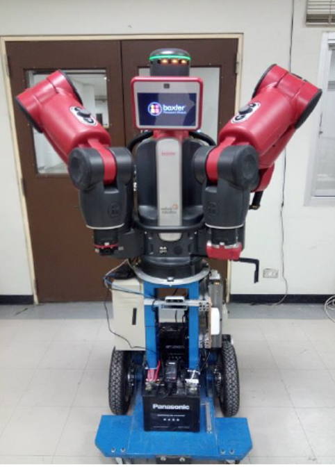
The overall system proposed in this research consists of a Baxter dual-arm mobile manipulator system that mounts on a differential drive two-wheeled mobile robot. Baxter robot is approximately 3 feet tall, and weighs approximately 75Kg and has two 7-DOF arms attached to it. Baxter has a vacuum gripper in the left arm and a parallel gripper in the right arm. Angle position and joint torque sensing are available with both arms. There are three integrated cameras located at the end effectors of each joint and the robot head.
The mobile robot system is controlled by Arduino MEGA 2560, which is communicated with the NVidia TX1 via the ROS Serial package. The system is driven using a couple of MY1016Z3 brushed DC motors, each controlled separately using ELMO-VIO 25/60 motor control units. The motor power is transmitted to the wheels via chain drives with the speed ratio of the motor to wheel 4.9:1. Since the motor controller requires an analog control signal to perform smooth motor controlling, MCP4922 Digital to Analog Converter (DAC) is used to generate the analog control signal from Arduino. The converter establishes an SPI communication between itself and Arduino with a frequency of 10MHz. Motor feedback is acquired using AMS’s ASP5147P absolute magnetic encoders communicate with Arduino via Serial Peripheral Interface (SPI) with the frequency of 1MHz. Readings from the encoder are recorded every 1ms using the Arduino timer 1 interrupts. Both the encoders and the Digital to the analog converter use the serial peripheral interface to communicate with the Arduino.
The vision system uses an Intel RealSense D435i depth camera and an Intel RealSense T265 tracking camera. In addition to that, Baxter’s right arm camera is used for the object manipulation process. Both RealSense cameras are mounted at the front frame of the mobile base. The two RealSense cameras are connected to the Nvidia TX1 via a USB hub, and Intel RealSense Linux drivers are installed to Nvidia TX1 to communicate with the cameras. Since all the vision tasks related to autonomous navigation and visual servoing will be carried out in the ROS environment, RealSense ROS wrapper libraries are used to collaborate RealSense cameras with ROS Simultaneous Localization and Mapping (SLAM) and navigation.
The entire system is operated using a 12V DC voltage that is powered by two 12V lead-acid batteries. Although the system runs on DC voltage, an AC voltage is required to operate the Baxter robot. It is achieved using a MeanWell TS1000 inverter.
Software Development
A cluster of software run inside the Nvidia TX1 development board along with an Ubuntu 18.04 operating system and a set of Jetpack 4.2 drivers installed. To operate the system, the Nvidia TX1 has to establish communication within all three subsystems simultaneously. ROS melodic software is used for this purpose. Baxter and Arduino SDKs are installed into the ROS workspace for programming and control. The vision system is communicated through RealSense SDK 2.35 and RealSense ROS wrapper.
Methodology
SLAM and Navigation
The mobile manipulator system is developed to autonomously navigate through a map while searching the target and transport the object to the desired goal location. Concept of the Simultaneous Localization and Mapping (SLAM) and navigation techniques are used to perform the autonomous navigation task. In this research, the ros_rtabmap package is used to perform the SLAM task.
Real-Time Appearance Based mapping which is shortly known as the RTAB-Map is a graph-based SLAM approach. In this approach, the map generation and the localization are done using the data collected from the D435i depth camera. RTAB-Map uses a process called loop closure detection to perform the localization by determining whether the robot has seen a location before based on the vision data saved in the RTAB-Map database. When the robot travels to alien areas in its environment, the map is expanded, and the number of images in the database increases. This causes the loop closure to take a long time along with the complexity increasing linearly. Therefore, RTAB-Map is optimized to handle the large data set to perform long-term SLAM by using the front-end and back-end SLAM approach. RTAB-Map can be used to generate a 3D map of the environment using 3D point cloud data and the RGBD data provided by the D435i depth camera, and odometry data provided by the T265 tracking camera. After creating the map using RTAB-Map, a “map server” package is used to save the data of the 2D map to be used for navigation.
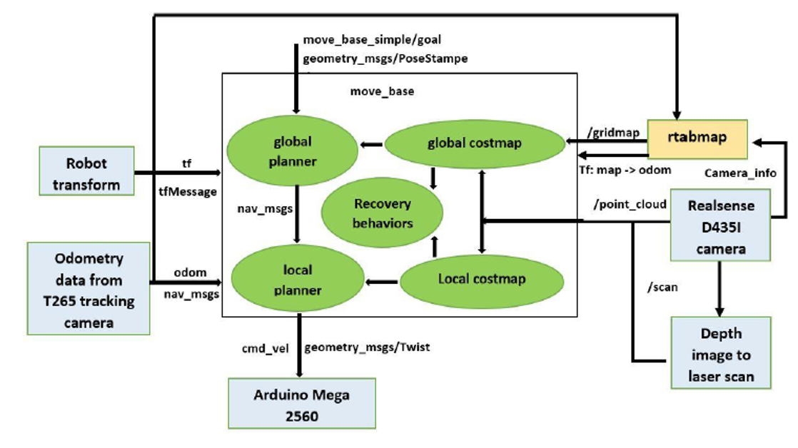
ROS Navigation stack configuration
Navigation
Map-based navigation is done using a configured ROS navigation stack according to the system requirement. The RealSense D435i camera is the main observation source of the navigation system. The RGBD data is used to perform the localization with the RTAB-Map while obstacle detection is done using the point cloud data and the fake laser scan data generated from the depth images of the D435i camera.
Localization and Path planning
RTAB-Map provides the localization during the navigation by finding the loop closure. The loop closure detector uses a bag-of-words approach to determine if a new image detected by the D435i camera is from a new location or from a location that has been already visited. This is done by matching the real-time image data with the image data saved in the rtabmap.db database during the map construction. Once a loop closure is found, the odometry is corrected and the real-time point cloud data is aligned to the map.
Path planning contains two sublevels known as the global planner level and the local planner level. For the global planner, the ROS global_planner library is used. The global_planner library is developed based on Dijkstra’s and A* algorithms. By experimenting, the TEB (Timed Elastic Band Approach) local planner is selected as the local planner of the navigation stack of the developed mobile manipulator system.
Development of Mobile Manipulation Strategy and system operation
The Aruco marker-based mobile manipulation technique is used in this system. Aruco marker is a binary square with a black background and a white generated pattern that uniquely identifies it. In this experiment, the Aruco markers are placed on the top and the front side of each box. Using these Aruco markers the position and orientation of the target box location are calculated. To detect the markers and estimate the pose a ROS python library is implemented based on the OpenCV Aruco library with the cv_bridge ROS package.
During the mobile manipulator system operation, the mobile manipulator navigates through the map by following the pre-defined waypoints on the map. When the robot reaches a pre-defined waypoint in the map, the robot starts to search the Aruco markers using the D435i camera. Once the marker is detected the robot reaches the target location and picks the object based on the aruco marker pose estimation. Then, the robot carries the object to the final goal location and place it at the final goal location. Finally, the robot reaches the initial position and terminates the operation.
Conclusion
- This system can be introduced as a reasonable and straightforward solution for basic mobile manipulation tasks in various industrial and domestic environments.
- Poor lighting conditions may cause a problem for the localization.
- In an empty area, the system cannot perform a precise localization due to the lack of data provided by the 3D camera to the RTAB-Map node. . However, the odometry provided by the RealSense T265 tracking camera reduces this error.
- The system cannot deal with dynamic obstacles present on the left, right, and rear sides of the robots. It may cause unnecessary collisions.
Future Works
- Introducing laser scanners will improve system navigation within a small area.
- The system can be further developed by introducing complex object manipulation techniques such as grasp planning, redundancy avoidance, and complex geometry manipulation.
- Introducing a close kinematic chain for this system will improve the system’s efficiency, allowing it to perform more sophisticated tasks.
- By introducing a more powerful computer to the system, the Aruco detection and the navigation can be performed at the same time which will reduce the total operation time thus increasing efficiency.
Acknowledgment:
This research was financially supported by The Royal Golden Jubilee Ph.D. Program (RGJPHD) Scholarship no. PHD/0101/2552 1.M.CM/52/G.1. The work was performed at the Motion and Control Laboratory, Chiang Mai University, Thailand.
Publication
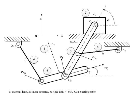
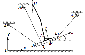
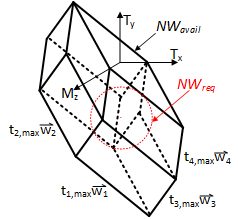
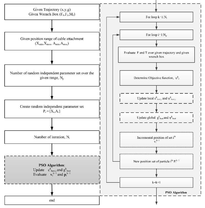
Chawalit Khanakornsuksan and Theeraphong Wongratanaphisan ”Optimal Design of a Hybrid Cable Driven Parallel Robot for Desired Trajectory and Force”, on 2018 International Conference on Mechatronic, Automobile, and Environment Engineering (ICMAEE 2018), Chiang Mai, Thailand, 7-9 July 2018
Chawalit Khanakornsuksan and Theeraphong Wongratanaphisan ”Design Optimization of a Suspended Cable-Driven Gait Generator using Three Cables”, on Joint Symposium on Mechanical-Industrial Engineering and Robotics (MIER 2017), Chiang Mai, Thailand, 16-17 November 2017
Chawalit Khanakornsuksan , Pinyo Puangmali and Theeraphong Wongratanaphisan,”Design of a Hybrid Cable- driven Foot Platform Device”, proceeding on The 5th TSME International Conference on Mechanical Engineering, Chiang Mai, Thailand, 17-19 December 2014