Adaptive Compliance Control Without Joint Velocity Measurement of Gait Training Robot for Neurological Patients

by Tarapong  Karnjanaparichat, Ph.D. student

Advisor: Assoc. Prof. Radom Pongvuthum

 Description of Project:

Many research studies have shown that patients losing motor control due to spinal cord injuries, stroke or other neurological injuries can regain their motor control if their limbs are trained to move in repetitive patterns. Manual treadmill training has been an established gait training method for over two decades. During the manual gait training, the patient has to be manually guided to produce a walk-like gait pattern by two or three physiotherapists placed next to the patient’s legs and pelvis. The patient is partially unloaded from the patient’s body weight and the legs as well as the pelvis are moved and guided by the physiotherapists. Therefore, the actual training duration and number of training sessions are limited, because this is a very tiring work for the therapists. Moreover, it is difficult to induce a constant and repetitive gait pattern during training. The induced gait pattern can be physiologically incorrect, because of the fatigue of the physiotherapists form training patients. In order to increase the duration of the training and to reduce the effort of the physiotherapists, the treadmill training has been automated.

The initial gait training robot developments are purely position-controlled. The patient legs are moved along predefined and fixed reference gait pattern. Muscle activity of the patient is ignored, and the patient legs are forced to follow a given gait pattern imposed by the robots. Recently, many researches are emphasized on improving the patient participation and the generation of afferent sensory input, which is the basis of the neurological recovery. Compliance is considered an important prerequisite for safe human-robot interaction. Due to their actuation system and control approach of gait training robots often lack of compliance. The patient may feel pain or uncomfortable. Adding compliance into the system can help in absorbing interaction forces and ensure safety of the patient.

Objective:

 The objective of this research is twofold:

  1. Build a gait training robot for training for patients with neurological injuries.
  2. Develop an adaptive compliance control scheme for a gait training robot without joint velocity measurement under the assumption those physical parameters of both human and robot, such as mass, inertia and friction, are unknown.

 Gait training robot Overview:

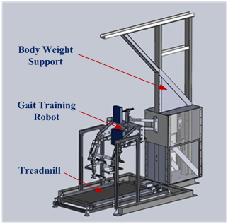
             The gait training robot system consists of a gait training robot, a treadmill and a body weight support device as shown in Figure 1. During the gait training, the robot, which is attached to the subject’s legs, will guide the legs to move in a predefined physiological gait pattern on treadmill.

Gait training robot
Figure 1. Gait training robot

 Robot Structure Design:

The gait training robot is designed as exoskeleton type, which is a two-leg robot with four DOFs as shown in Fig. 2. Each hip and knee joint is a revolute joint, which can flexion and extension movements in the sagittal plane. The mechanical ranges of the hip and knee joints are from -45 to 35 degrees and 0 to 65 degrees respectively. The robot is equipped with a ball screw actuator to drive each joint. Joint motion of each joint is calculated form  measuring signals of a potentiometer as installed at each joint shaft and an encoder as installed at the end of each joint’s actuator.       There are three load cells at cuffs for each robot leg in order to measure interaction forces from a subject leg. The interaction forces are used to make compliance into the robot control between the training.

Moreover, the robot can be adjusted parts for fitting each subject body as follows. The upper and lower robot leg lengths can be adjusted from 350 to 480 mm and 290 to 380 mm respectively. The pelvic width and back and pelvic cushions can be also adjusted for the subject’s comfortable. The cuffs can be adjusted for appropriating each subject leg.

Components of the gait training robot
Figure 2. Components of the gait training robot

Controller implementation:

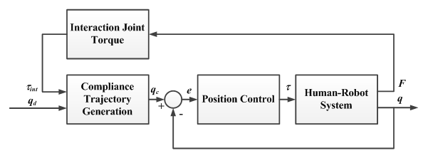
The control scheme consists of two parts in Fig. 3. First, the desired hip and knee gait trajectories are fed to a virtual spring-mass-damper model to generate reference hip and knee trajectories for a position controller in second part. The reference trajectories allow to be deviated from the desired gait trajectories depending on interaction forces between the patient and the robot. The reference trajectories are then fed to the position controller.

The control scheme provides compliance to muscle forces from a patient. The virtual spring-mass-damper model of each leg can be arbitrarily specified to achieve desired compliant dynamic behaviors to provide optimal trade-off between the patient’s safety and gait performance.

Compliance control diagram
Figure 3. Compliance control diagram

Publications:

  •  T. Karnjanaparichat and R. Pongvuthithum, “Dynamical Analysis for Mechanical Design of Gait Training Robot”, The 26th Conference on Mechanical Engineering of Thailand (ME-NETT 26), 27 October 2012.

Acknowledgment:

This project is supported by National Electronics and Computer Technology Center (NECTEC), Thailand.

Workspace Synthesis of an Asymmetric Delta Robot

By Wasin Wongkum
Advisor: Assoc. Prof. Theeraphong Wongratanaphisan

Delta Robot

Delta Robot is a popular parallel robot which has 3 degree-of-freedom. It is used widely for packaging industry. The advantages of the Delta robot are high strength, high agility, low inertia and high precision making it suitable for high-speed & high-precision applications. Typically, parallel robot has complicated kinematic. However, the kinematic of Delta robot is quite simple.

Most Delta robots are symmetric in its structure i.e., each legs is installed on the base 120 degrees apart. For this the workspace of the robot is symmetric. However, in some applications, it may occur that the task space are not necessarily symmetric. This project focuses on synthesis of an asymmetric Delta robot.

Delta
Objective

  • To study effects of the kinematics and workspace of the Delta robot which has different arm length and arm angles.
  • To synthesize an asymmetric Delta robot optimized for a certain workspace.

Praween Shinonawanik

  • Field of Interest: Control of inherently unstable systems, Orientation estimation algorithm
  • Thesis Title: Control of Two-wheel Balancing Robot with Unknown Center of Mass
  • Degree: M.Eng (Mechanical Engineering), 2013

Sopit Nondjuy

  • Field of Interest: Robotic and Stability Control
  • Thesis Title:  Design and Balancing Control of Bicycle Using Reaction Wheel
  • Degree: M.Eng (Mechanical Engineering), 2015

” If you don’t stand for something, you’ll fall for anything.”– – Anonymous – –

Pinyo Puangmali, Asst. Prof.

  • B.Eng (Mechanical Engineering), Chiang Mai University, Thailand (1999)
  • M.Sc. (Mechatronics), University of Siegen, Germany (2004)
  • Ph.D. (Mechanical Engineering), King’s College London, UK (2011)

Office: ME2
pinyo@dome.eng.cmu.ac.th

ROBUST CONTROLLER DESIGN FOR CHATTER SUPPRESSION IN MACHINING USING INTEGRATED CUTTING AND FLEXIBLE STRUCTURE MODELS

by Prapon Ruttanatri, Ph.D. student

Advisor:  Assoc. Prof. Dr. Matthew O.T. Cole

Description of project

Active control of structural vibration in machining processes to prevent dynamic instabilities and chatter is the main issue for this project. A controller design is proposed based on a multi-mode description of flexible structure dynamics combined with cutting process equations that capture time-delayed feedback effects. A method for robust delayed-state feedback control synthesis is presented based on Lyapunov-Krasovskii functionals (LKFs).

Objective

To develop and compare controller design methodologies for active control of regenerative vibration in machining processes in order to improve/increase operating regions for stable cutting. The main focus is on the use of modern robust controller design methodologies and new techniques for controller design based on combined models of machine structure flexibility and cutting force generation mechanisms.

Hardware-in-the-loop evaluations overview:

The experimental system used for this study (Fig. 1) has been designed to exhibit two main structural resonances and is dynamically similar to an AMB-equipped milling spindle that exhibits significant cutting tool flexibility. The main structure is a flexure-pivoted beam connected to an end-mass through another flexure pivot. Two non- contact electromagnetic actuators are used to apply forces to the structure. Hardware-in-the loop simulation and controller testing for machining vibration can be undertaken based on the configuration shown in the block diagram Fig. 2. In this scheme, actuator 2 is an auxiliary actuator used to apply a simulated cutting force that is computed in real-time using a cutting force model implemented within the control hardware. This also requires real-time measurement of the “tool” displacement. Actuator 1 is the control actuator and is used to apply the stabilizing control forces. Note that, as the cutting force model is implemented digitally on the control hardware, the cutting model can be selected freely, subject to limits of actuator force capacity and bandwidth. Displacement of the structure can be measured by two non-contact sensors positioned close to the actuators. Additional vibration measurements are obtained by strain gauges at the flexure locations. Integration of strain sensing in spindle bearing guides has been considered for the purpose of tool deflection compensation. However, in the present case the signals provide dynamic state information related to tool deflection that can be used for feedback control of vibration. Displacement measured at the cutting location is used for calculation of the simulated cutting force but is not used for feedback. Full state information is obtained by combined use of the displacement and strain sensors located away from the “tool” end.

Figure 1. Main components of test system for experiments on active vibration control of machine structures.
Figure 2. Operating principle of test system for experiments on active vibration control of machine structures.

Publication:

  • Prapon Ruttanatri, Matthew O.T. Cole and Radom Pongvuthithum, “Stabilizing Active Vibration Control of Machining Processes Based on Lyapunov-Krasovskii Functionals for Time-Delay Systems”, The 7th TSME International Conference on Mechanical Engineering, Chiang Mai, Thailand, page no. 152, December 13-16, 2016
  • Prapon Ruttanatri, Matthew O.T. Cole and Radom Pongvuthithum, “Structural vibration control using delayed state feedback via LMI approach – with application to chatter stability problems” SAGE

Acknowledgement:

This work was partly supported by the RGJ-PhD scholarship program under the Thailand Research Fund (grant number PHD/0089/2553).

Active control of rotor systems to prevent instability arising from non-linear rotor-stator interactions

Chakkapong Chamroon and Assoc. Prof. Dr. Matthew O.T. Cole

Project description:

When a machine rotor is running through critical speeds, there is a chance of rub with its stator. This may lead the machine to malfunction or cause damage. If rub behaviour can be predicted accurately then this failure may be prevented. The Lyapunov stability condition based on state space model approach will be considered in this research because it is able to treat non-linear elements and ensure that the stability of system is preserved. It can deal with multiple non-linear feedback terms. The overall aim of this research will be to develop stability criterion based on state space models and control strategies which can be implemented on a real machine for preventing rotor-stator contact instability.

contact_scheme
Figure 1 Schematic diagram of flexible rotor-stator system showing cross-section where interaction between rotor and surrounding part occurs.

Focus:

This work focuses on active vibration controller design to stabilize a rotating machinery undergoing contact between rotor and stator. The controllers are designed for an active magnetic bearing actuator and are based on Lyapunov stability criteria of the contact-free orbits.

CAD_model
Figure 2 CAD model of rotor-stator system.

Check this video tube for result:

 Sponsors:

  1. Office of the Higher Education Commission of the Royal Thai Government
  2. The Thailand Research Fund

 Publications:

C. Chamroon, M.O.T. Cole and T. Wongratanaphisan, “An active vibration control strategy to prevent nonlinearly coupled rotor-stator whirl responses in multimode rotordynamic systems”, IEEE Trans. Contr. Syst. Technol., available online DOI 10.1109/TCST.2013.2265740.

M. O. T. Cole, C. Chamroon, P. Ngamprapasom, “Forcefeedback control for active stabilization of synchronous whirl orbits in rotor system with nonlinear stiffness elements”, ASME J. Vib. and Acoust., vol. 134, no.2, 021018, 2012

 Conference Proceedings:

Chakkapong Chamroon, Matthew O. T. Cole, Theeraphong Wongratanaphisan and Radom Pongvuthithum, “Achieving Globally Stable Active Vibration Control in Nonlinear Rotordynamic Systems”, International Graduate Research Conference, Chiang Mai, Thailand, December 20, 2013.

Chakkapong Chamroon, Matthew O. T. Cole and Theeraphong Wongratanaphisan, “An active vibration control strategy to prevent friction-driven backwards whirl in rotordynamic systems”, The 4th TSME International Conference on Mechanical Engineering, Pattaya, Thailand, October 16-18, 2013.

Simultaneous Optimization of Structure and Control for Time-Optimal Motion of Vibratory Mechanical System

by Boonruk Suchaitanawanit, Ph.D. student

Advisor: Assoc. Prof. Matthew Cole

Time-Optimal Control

Nowadays many engineering operations require rapid movement with high precision. To acquire maximal speed of motion, an extreme value of actuation effort is employed which could lead to excitation of the flexible mode causing undesired vibration. The time interval can be minimized by a bang-bang control. However, with correct timing of switching action. vibration can be minimized. In this research, we focused on finding the correct timing for the switching action whist minimizing the interval of motion. Real world applications of time-optimal control includes motion of the flexible structures are such as hard-disk drive, crane and spacecraft structures.

 Structural Optimization

Conventionally, mechanical structure design and controller design are separate procedure. By combining two processes together, a better performance of the system could be achieved. A structure whose parameters are compatible with the tasks, might achieve better time performance the one that are not. The selected case study in this research involves tuning a stiffness of the flexible structure to match with the travelling distance associate with time-optimal motion.

Objective

The objective of the project is to develop a new mathematical strategy based on the convexity of the reachable set in order to solve time-optimal control problem. The proposed algorithm can guarantee the true optimality of the control solution since it solves directly for co-state variables which satisfy the necessary conditions rather than searching for switching time and later verify the optimality by using Pontryagin’s Minimum Principle. Figure 1 shows the example of the reachable set of 3 states linear model of the flexible structure.

Figure 1. Reachable set of flexible structure in 3D

The system along with time-optimal control solutions acquired by the proposed algorithm will be tuned to achieve even faster motion. The tuning algorithm uses iterative scheme to alter the structural parameters and control profile in order to reduce the motion interval. By exploiting the continuity of the reachable set the iterative tuning method based on the steepest descent gradient searching is able to move toward the local minimum.

The obtained solution was verified and applied on the experimental rig (fig. 2). Here linear translation of the crane-like structure with flexible armature is to provide vibration free rest-to-rest motion. Solution are shown in figure 3. The rig has tunable stiffness mechanism which allows natural frequency and damping ratio of the flexible link to be tuned for verifying the simulation results.

Figure 2. Experimental rig
Figure 3. Typical time-optimal control solution of the test rig

Publication

  • B. Suchaitanwanit and M.O.T Cole, “An Algorithm to Obtain Control Solutions Achieving Minimum-Time State Transfer of Linear Dynamical System Based on Convexity of The Reachable Set”, In Proceeding of the 4th International Conference on Intelligent Systems, Modeling and Simulation, Vol. 1, pp. 340-345, 2013.
  • B. Suchaitanwanit and M.O.T Cole, “Fundamental Limit of Performance in Minimum-Time Motion Control due to Structural Flexibility”, In Memoirs of Muroran Institution of Technology, Vol. 6, pp. 7-12, 2013.

The project is partly support by Royal Golden Jubilee (RGJ) project under care of Thailand Research Fund (RGJ).