Optimal Design of a Cable Driven Locomotion Device

Chawalit Khanakornsuksan, Ph.D. student

Assoc. Prof. Theeraphong Wongratanaphisan

Description of Project:

Parallel Kinematic Manipulators (PKM) have gained wide attention over past decades. Many researchers have developed PKMs to overcome some limitation of traditional serial robots. However, there are major drawbacks of PKMs such as small workspace, low dexterity and singularities. These are challenging problems that need to be addressed during the design. Cable Driven Parallel Robots (CDPRs) are a special class of PKMs whose actuated limbs are cables instead of rigid-linked actuators. All cable are attached to a mobile platform which hosts robot’s end-effector and the other ends are wound in fixed reels installed on a fixed base. Positions and orientations of the mobile platform can be attained by controlling the length of those actuating cables. The benefits of the cable actuation are its simple form of producing force, light weight, and relatively large actuating range resulting in large workspace. One of the promising applications of CDPRs is for the design of locomotion device as it can provide wide motion range with very light weight.

Objective:

As the cable-driven parallel robot has great potential for use in many applications, this study aim explorer that possibility. The purpose of the study is two fields:

  1. To introduce the new gait mechanism concept which is driven by cables in an end-effector type configuration. Conceptually, the user places their feet on a moving platform which is driven by a number cables during the gait motion. This machine can generate 3 DOF motion of the moving platform: ( x- and y- position and orientation in a vertical plane). The robot would be designed to suit rehabilitation task which is to produce a smooth gait motion for user with different physical parameter such as height and weight.
  2. Derive a method to optimally design the cable-driven gait generating mechanism. The outcome of study should allow us to indicate, in an optimal sense, what the locations of the cable attachment point on the moving platform and ground should be. The design targets are defined in terms of reducing cable tensions under applied external forces from user weight during the motion. Uncertainties due to external forces applied on the platform will be taken into account.

Scope of the study

  1. Analyze the gait motion and propose a suitable configuration of cable-driven gait generating mechanism which will be a platform for study. The study focuses on a non-redundant type cable-driven robot.
  2. Optimally determine the location of cable attachment points using PSO optimization technique.
  3. The motion of the mechanism is confined to a vertical plane.

Assumptions

  1. The weight of the cable will be neglected. Hence it will be assuming in the kinematic and force analyses that the cables are adjustable length linear elements.
  2. The moving platform is considered as a rigid body.

Optimal Design of a Hybrid and Fully Cable Driven Parallel Robot

In this thesis, two new automated gait mechanisms based on a cable-driven parallel kinematic mechanism are introduced: 1) a hybrid cable driven robot with 2 cables and one rigid moving link and 2) a 4-cable planar parallel robot (4CDPPR). Both mechanisms can generate three degrees of freedom (DOF) gait pattern motion of a moving platform (two translational and one rotational motion in a vertical plane) for normal walking gait.

Figure 1 A configuration of the hybrid cable driven robot

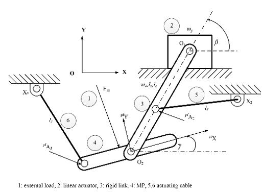
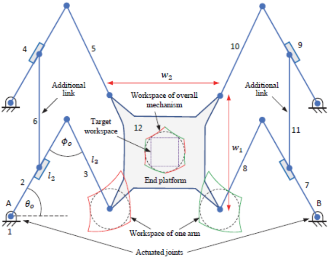
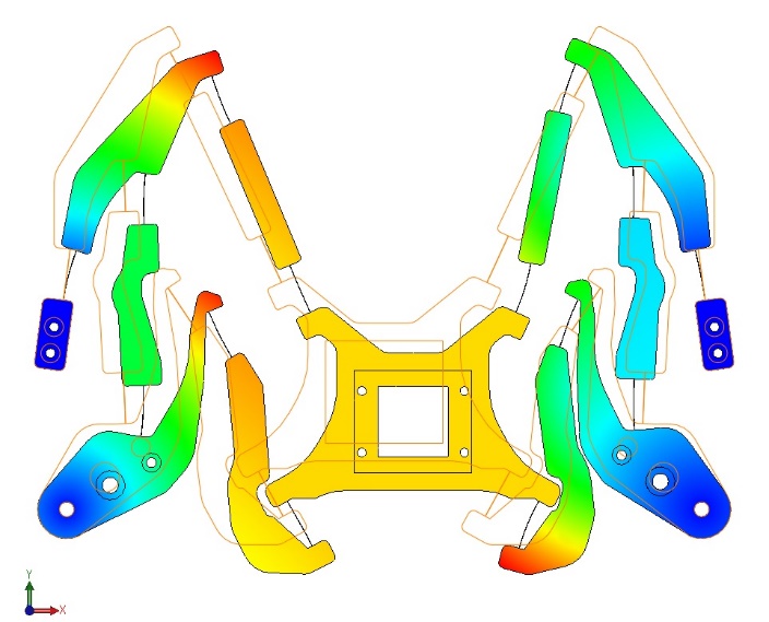
The first proposed mechanism, called the “hybrid cable driven planar parallel robot (HCDPPR)” , Fig. 1, was designed with two cable and one rigid link in order to maintain the number of degrees of actuation equal the number of degrees of freedom. The cables were designed to take only the tension force and the rigid link can take both tension and compression loads. A method was proposed to optimally locate the cable attachment points on ground and moving platform while keeping the cable tensions minimized in optimal sense. With the current design configuration, the results suggest that the cable attachment points on the ground should be at the waist level and the cable attachment points to the foot support should be below the joint of the connecting rod. In this configuration, constraints on optimized parameters were also be imposed in order to avoid cable and user interference.

Figure 2 A sketch of suspended 3 cables with human’s leg

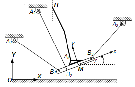
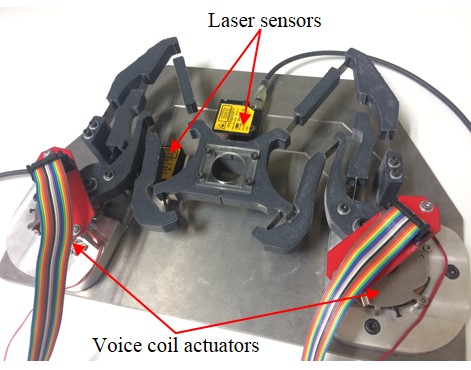
The second proposed mechanism employed only cables as actuating members. A method for the gait generating dimensional synthesis of cable driven planar parallel robots mechanism was proposed, Fig. 2. Two configurations have been considered. Firstly, a suspended 3-cable mechanism which makes use additional force from gravity as a virtual cable downward force. To optimally locate the attachment point, Particle Swarm Optimization (PSO) algorithm has been used to minimize cable tensions. The results showed that the optimal cable attachment locations are usually very high above ground which made structure of the mechanism very large and unrealistic. Due to the limit of space for installation, the range of cable attachment parameters are reduced to realistic values. In addition, to avoid body interference, the safety boundary constraints are included in the optimization algorithm.

Figure 3 The polyhedral concept to enclose the desired wrench closure

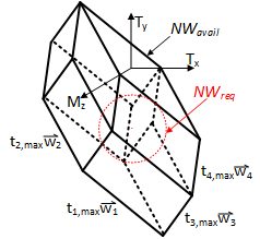
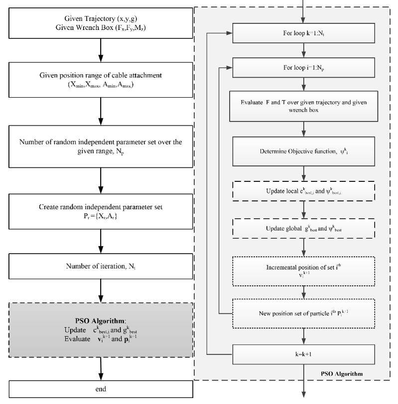
Realistically, the mechanism must be designed to take into account the range of unpredictable external forces that can act on the platform. The concept of graphical representation by polygon is applied to optimization algorithm to find the minimal polygon’s shape which can cover the desired wrench. The 4CDPPR system was used to show the behavior of the algorithm concept. For the whole range of motion, two wrench boxes were used to represent two different level of external force range (high and low) separated by two regions. The high-force region corresponds to the stance phase and the low force region represents the swing phase. In the optimization process we first randomly select the optimized parameters that a wrench closure workspace (WCW) exists. This will ensure that solutions for the polyhedra to enclose the wrench boxes can be found, Fig. 3. Then the PSO algorithm, Fig. 4, was set to begin finding the optimal parameters. It was shown that the proposed method that solutions in wrench feasible workspace (WFW) may be found by relaxing the size of the polyhedra. The size of polyhedra is related to the magnitude of maximum cable tension used in the objective function. By reducing the size of the feasible polyhedra, the optimal tension force can be obtained. Finally, our intuition is that the same approach can be applied to the dimensional synthesis of other prescribed trajectories as well as fully constrained systems with arbitrary number of cables.

Figure 4 PSO algorithm concept for N_p particles and N_k iterations

Acknowledgment:

This research was financially supported by The Royal Golden Jubilee Ph.D. Program (RGJPHD) Scholarship no. PHD/0101/2552 1.M.CM/52/G.1. The work was performed at the Motion and Control Laboratory, Chiang Mai University, Thailand.

Publication

Chawalit Khanakornsuksan and Theeraphong Wongratanaphisan ”Optimal Design of a Hybrid Cable Driven Parallel Robot for Desired Trajectory and Force”, on 2018 International Conference on Mechatronic, Automobile, and Environment Engineering (ICMAEE 2018), Chiang Mai, Thailand, 7-9 July 2018

Chawalit Khanakornsuksan and Theeraphong Wongratanaphisan ”Design Optimization of a Suspended Cable-Driven Gait Generator using Three Cables”, on Joint Symposium on Mechanical-Industrial Engineering and Robotics (MIER 2017), Chiang Mai, Thailand, 16-17 November 2017

Chawalit Khanakornsuksan , Pinyo Puangmali and Theeraphong Wongratanaphisan,”Design of a Hybrid Cable- driven Foot Platform Device”, proceeding on The  5th TSME International Conference on Mechanical Engineering, Chiang Mai, Thailand, 17-19 December 2014

Development of a Computer Program to Assist Upper Limb Rehabilitation Using Kinect Camera

by Peng Nan, Master. student

Advisor:  Assoc. Prof. Dr. Theeraphong Wongratanaphisan

Description of Project:

Traditional way of upper limb rehabilitation to use upper extremity rehabilitation equipment for training the proximal upper extremity movement functions. They are essential tools in the occupational therapy (OT) practice. Most existing clinical provides no feedback to the patients. Patients may find that repeating the same activity can be boring and monotonous and thus develop a negative attitude toward the therapy process. In order to increase the mental satisfaction and physical vitality of rehabilitation therapy, some therapists have using off-the-shelf video game systems in rehabilitation. Digital games have been proven effective in upper extremity rehabilitation for patients in addition to arousing higher motivation and feelings of pleasure.

The Kinect operates in real-time, it is different from traditional physical-based equipment, there is no need to carry any sensor on the body, and the player only needs to face Kinect lens, and the chip inside it will then calculate the joint information of the skeleton of each player. This technology allows user images to appear in the stimulated environment and presents an interactive interface. The technology of creating real-time computer simulated environment for the user is known as Virtual Reality. Conventional methods of rehabilitation being monotonous and barely followed by patients, so the Virtual Reality based exercise game creates new rehabilitation approach. Conventional therapy does not provide feedback to the patients and hence no motivation. Exercise game delivers feedback to patients during gameplay and motivate patient to perform exercises in correct manner. Therefore, this study proposes Kinect based real time shoulder joint angle measurement and healthcare exercise game can be used for rehabilitation. The angle measurement application can also be used as an alternative method for measurement of shoulder flexion and abduction angles.

Objective:

  1. To evaluate the performance of Kinect sensor for use in rehabilitation task.
  2. To develop a computer program using Kinect sensor for human upper-limb exercise.

Kinect-based Interactive Games overview:

The program user interface is shown in Figure 1. There are two users of the system:  The first user is the patient. The patient plays the game in front of the Kinect device. The patient’s data are then streamed to the developed system for game processing and data recording. The patient can see own images in the virtual world from the monitor screen during playing game. The game is designed to make the patient perform game tasks that encourage movement of one arm in prescribed motions that help rehabilitation progress. The second user is the operator (physiotherapist). The operator will perform setting-up task such as input patient’s data into the system, review the patient’s previous record of treatment and make a judgment for the current treatment though game difficulty level. After the rehabilitating session, the operator review the outcomes of current treatment returned from the program in the form of game score. The operator then makes judgement on the pan of next rehabilitating session.

The system is designed according to the following features:

  • Simple user interface: the software should have a simple user interface, which is clear, simple to use at first sight, and has unambiguous meaning for the user.
  • One patient for one-time period: during the practice only one person was standing in front of the Kinect sensor, only his/her movement should be processed.
  • Therapist-assisted set-up: the software is set up by the therapist adapted to the patients’ needs and the therapist controls the whole practice. The control of the program is not the patients’ task.
  • Data review and record: after every treatment session the opportunity to save the results should be provided. The saved quantitative data should include the date, the concrete tasks, with how many repetitions and how many successful repetitions the patient completed the tasks, game score, the range of joint angle movements in order to monitor the progress of the system.

Publication:

  • Peng Nan and Theeraphong Wongratanaphisan “Kinect-based Interactive Games with Joint Measurements to Assist Upper Limb Rehabilitation”; The 12th International Convention on Rehabilitation Engineering and Assistive Technology 14-16 July 2018 in Shanghai, China.

Acknowledgement:

This work was partially supported by Chiang Mai University.

Universal Control Designs for Time-Delay Uncertain Non-Linear Triangular Systems

by Kanya Rattanamongkhonkun, Ph.D. Student

Advisor: Assoc. Prof. Dr. Radom Pongvuthithum

Research Overview

Control designs for nonlinear systems have been studied for a few decades. More and more researchers are interesting in nonlinear control systems. This is because nonlinearities naturally arise in many physical systems such as robotic systems, physical systems with friction, chemical processes and economics model with chaotic behavior.

Even though, there are many techniques that allow linear control design to be applied to nonlinear system, they often involve some forms of approximation such as linearization and treating the nonlinear terms as disturbances or assume that the nonlinear terms is precisely known so that feedback linearlizable is applicable. Therefore, unless the parameters or the structures of the nonlinear system are precisely known, global stability usually cannot be proved. Moreover, there are several types of systems that cannot be stabilized by linear control law. A well-known example is a class of chain of power integrators, a lower triangular system which the power of states in the chain of integrators are not equal to one. This class of system cannot be stabilized by any linear controller even locally since the linearized system might have unstable and uncontrollable modes. In addition, employing nonlinear control design can achieved a different type of stability such as finite-time stability. This type of stability cannot happen in a linear system since the system trajectories will be equal to zero in finite time. This implies that the solution of the system is not unique.

Practically, it is very difficult to obtain an exact model of a real system. This may be due to the lack of actual information of the real system, changing of parameters values due to different environment operation, or even deterioration of the system over time, etc. Thus, system models usually contain errors or uncertainties.

Another interesting topic in control is time-delay nonlinear uncertainties. This phenomenal can be found in chemical process where a system of chemical reactor can be modeled as a nonlinear system with time-delay uncertainty. Also, the time-delay can be found in machining processes such as milling process and turning. Although, in machining processes, the time-delay can be measured from the spindle speed, cutting speed can be varied greatly.

In this work, we focus on designing a control law which can deal with both nonlinearly unknown parameters and time-delay uncertainties in the same time. Moreover, our control design is not only able to handle the time-delay uncertainties but is independent of time-delay information which is more robust and flexible in the implementation.

Objective

To construct a time-delay free controller for a class of time-delay triangular systems with nonlinearly unknown parameters which can guarantee the boundedness of all closed-loop trajectories and convergence of the system states.

Publications

  • Pongvuthithum, K. Rattanamongkhonkun and W. Lin. “Asymptotic regulation of time-delay nonlinear systems with unknown control directions.” IEEE Transaction on Automatic Control, vol. 63(5), pp. 1495-1502, 2018. doi:10.1109/TAC.2017.2748898.
  • Rattanamongkhonkun, R. Pongvuthithum and W. Lin. “Nonsmooth feedback stabilization of a class of nonlinear systems with unknown control direction and time-delay.” International Journal of Robust and Nonlinear Control, (Accepted), 2018. doi:10.1002/rnc.4317
  • Wei Lin, K. Rattanamongkhonkun and Radom Pongvuthithum. “LgV-type adaptive controllers for non-affine systems with parametric uncertainty.” IEEE Transaction on Automatic Control, (Accepted)
  • Rattanamongkhonkun, R. Pongvuthithum, W. Lin and G. Tao. “Feedback stabilization of nonlinear systems with unknown control directions and time-delay.” Asian Control Conference (ASCC 2017), pp. 138-143 2018. doi:10.1109/ASCC.2017.8287156. Gold Coast Convention and Exhibition CentreGold Coast, Australia, December 17-20, 2017.
  • Rattanamongkhonkun, R. Pongvuthithum and W. Lin. “global stabilization of a class of time-delay nonlinear systems with unknown control directions by nonsmooth feedback.” IFAC-PapersOnLine, vol. 51(14), pp. 78-83, 2018. doi:https://doi.org/10.1016/j.ifacol.2018.07.202. 14th IFAC Workshop on Time Delay Systems (IFAC TDS 2018), Budapest, Hungary, June 28-30, 2018.
  • Wei Lin, K. Rattanamongkhonkun and Radom Pongvuthithum. “Adaptive stailization of cncertain non-affine systems with nonlinear parameterization.” 18th IFAC Symposium on System Identification (SYSID 2018), Stockholm, Sweden, July 9-11, 2018.

Acknowledgement

This work is supported by The Royal Golden Jubilee Ph.D. Program (RJG).

Modelling and control of a flexure-jointed servo-mechanism

Pongsiri Kuresangsai, Ph.D. student

Advisor: Prof. Dr. Matthew O.T. Cole

Description of Project:

Conventional mechanisms, used to transfer energy, forces or generate desired motion, are constructed by connecting links using joints with rolling or sliding parts. This introduces effects such as backlash and friction, which can compromise the accuracy at micrometer scales. To overcome these effects, monolithic mechanisms may be constructed having compliant flexure-based joints that can achieve motion with higher repeatability and fidelity, even to sub-micron levels. Such compliant mechanisms have a number of other advantages. They require a reduced number of parts and can be made by single-process manufacturing such as 3-D printing or electric discharge machining. Constructing a mechanism as a single piece can also reduce time and costs. Flexure-based joints suffer less from wear or contamination and do not require lubrication. Even though flexure-jointed mechanisms can give high accuracy motion, the range of motion is limited by the elastic limit of the joints under deflection. Also the dynamic and kinematic behavior is more complex. For such mechanism, the analysis and optimization of designs is challenging.

Objective:

  1. To develop and verify non-linear dynamic models of the proposed mechanism
  2. To consider the design and application of controllers based on linearized models of the mechanism
  3. To investigate enhancing dynamic performance by utilizing non-linear dynamic models of the mechanism within the controller design procedure
  4. To implement and test controllers on the experimental system to verify and compare performance

Research overview

Many researchers have considered the design of flexure-based mechanism having workspace in micrometer scale. For widening the range of applications of flexure mechanism, we focus on designing flexure mechanism having large workspace in cm-scale but with compact mechanism that can operate at high accuracy for a large number of motion cycles.

A case study was undertaken involving the optimized design of a mechanism inspired by a having conventional five-bar linkage 2 DOF in XY plane and with 2 actuators. We use uniform beam joint to replace revolute joint because it is relatively simple to model and design and has good characteristics to achieve increased working area with low stress concentration.

In any equilibrium position for the flexure mechanism, the platform will rotate due to acting forces and bending moment applied through the connecting flexures. It is therefore desirable to design a mechanism for which rotation of the platform is as small as possible.

To undertake design optimization for flexure jointed mechanisms the use of nonlinear FEA models is possible. This can give high accuracy prediction of motion but is very computationally intensive. Therefore, a novel modelling approach having high accuracy even at large deformation configurations was developed. This approach was extended and applied for design optimization of a complete mechanism. The aim was to prevent rotation of the platform as much as possible. To validate the suitability of the proposed flexure modelling approach, result have been compared with nonlinear finite element method. The FEM results

then agreed closely with modelling approach, although a high accuracy FEM computation took approximately two hours compared with less than 10 seconds. Experimental results for  the X-Y stage confirmed the effectiveness of the optimized design.

In the proposed work, this flexure modelling approach will be extended for use in dynamic models of the whole mechanism. Verification of the model can be made by frequency response testing approach. As the dynamic model will be complex and have some uncertainty a robust control approach will be required.

Figure 1: Conventional five-bar linkage 2 DOF in XY plane and with 2 actuators
Figure 2: Realization of flexure-jointed X-Y motion stage. FEM results for bottom-right platform positioning are shown.
Figure 3: Experimental setup for flexure-jointed X-Y motion stage.

Acknowledgment:

This work was partially funded by the Chiang Mai University Mid-Career Research Fellowship program and Center of Mechatronic System and Innovation. Pongsiri Kuresangsai was supported by the RGJ-PhD scholarship program under the Thailand Research Fund and by a Ph.D. Studentship and TA/RA Scholarship from the Graduate School, Chiang Mai University. 

Analysis and Design of Parallel Robot for Arm Rehabilitation

by Amnad Tongtib, Ph.D. student

Advisor: Assoc. Prof. Dr. Theeraphong Wongratanaphisan

 Description of Project:

Patients who cannot move part of body from accident, medical surgery, injury form sport playing, spinal cord injury or clogged arteries, require recovering. From this reason, the patient will be rehabilitated by physical therapist. In rehabilitation, the patient generally requires close care from a physical therapist. However, the rehabilitation tasks are repetitive over lengthy time. This causes physical therapists to be tired. From this reason, concept of using robot(s) to assist physical therapists is appealing.
Rehabilitation with robots can be divided into two main area: leg and arm. The leg rehabilitation includes hip, knee and ankle part and the arm rehabilitation includes shoulder, elbow, forearms, wrists and finger part. There are two main types of rehabilitation robot: exoskeleton robot and end-effector type robot. The exoskeleton robot employs serial mechanical structure that align with part of body to be treated, leg or arm. The joints of the robot must be aligned with rotation of joints of the body to generate the motion. For example, if we want to treat legs (hip and knee), we will use two-link serial mechanism attached to the leg. The motor will be attached to align with the hip joint and the other motor will align with the knee joint. Then, the robot will operate with pre-specified joint-space motion. In the end-effector type, the end-effector of the robot is attached to the body part and take this part to move in pre-specified path in three dimensional space. Advantage of this type is that the robot does not necessary to attach to many locations on the body part as in exoskeleton type. Therefore, the patient feels more comfortable. In this project, the parallel robot for arm rehabilitation will be analyzed, designed and built.

Objective:

1. To analyzes and design parallel robot for arm rehabilitation.
2. To study and design smooth path generation of the robot for arm rehabilitation.
3. To study algorithm for designing a 3-legs parallel robot with optimization technique.

 Gait training robot Overview:

           In establishing arm rehabilitation robot, mechanism of the 3- parallel robot is used to build the robot. Moving platform connected to fixed base with three link chains (or leg), each leg consist of two rigid body (lli and lui) which connected by revolute joint, end of leg connected to moving platform with gimbal joint (spherical joint is replaced with gimbal joint because range of motion of gimbal more than spherical joint) and the other end connected to base with two actuators. The robot has six actuators which are brushless DC motors. Two motors in each leg are installed at the fixed base with the perpendicular direction. At center of moving platform, we install the handle to catch the patient’s hand. Mechanism of the robot is shown in Figure 1.


 Robot Structure Design:

The gait training robot is designed as exoskeleton type, which is a two-leg robot with four DOFs as shown in Fig. 2. Each hip and knee joint is a revolute joint, which can flexion and extension movements in the sagittal plane. The mechanical ranges of the hip and knee joints are from -45 to 35 degrees and 0 to 65 degrees respectively. The robot is equipped with a ball screw actuator to drive each joint. Joint motion of each joint is calculated form  measuring signals of a potentiometer as installed at each joint shaft and an encoder as installed at the end of each joint’s actuator.       There are three load cells at cuffs for each robot leg in order to measure interaction forces from a subject leg. The interaction forces are used to make compliance into the robot control between the training.

Moreover, the robot can be adjusted parts for fitting each subject body as follows. The upper and lower robot leg lengths can be adjusted from 350 to 480 mm and 290 to 380 mm respectively. The pelvic width and back and pelvic cushions can be also adjusted for the subject’s comfortable. The cuffs can be adjusted for appropriating each subject leg.

Figure 1. Description parallel robot for arm rehabilitation


Publications:

  • Amnad Tongtib and Theeraphong Wongratanaphisan “Concept for Using a 6-DOF Parallel Manipulator In Passive Upper Limb Rehabilitation”; The 12th International Convention on Rehabilitation Engineering and Assistive Technology 14-16 July 2018 in Shanghai, China.
  • Amnad Tongtib and Theeraphong Wongratanaphisan “Kinematic analysis and Workspace Analysis of a 3- Parallel Robot’’; Joint Symposium on Mechanical-Industrial Engineering, and Robotics 2017(MIER2017) 16-17 November 2017 in Chiang Mai, Thailand
  •  Amnad Tongtib, Pinyo Puangmali and Theeraphong Wongratanaphisan “Kinematic analysis of a 3- Parallel Robot’’; The 7th TSME International Conference on Mechanical Engineering, 13-16 December 2016 in Chiang Mai, Thailand.

Acknowledgment:

This project is partially supported by 1) Mid-Career Researcher Grant, Chiang Mai University and 2) the Center Mechatronic System and Innovation, Chiang Mai University.